A car-sense belt-sense detection integrated machine Part
Compared with the prior art, the beneficial effects of the present utility model are:
1、In the utility model, the power provided by the first hydraulic rod is provided to cooperate with the first clamping block and the first connecting plate, so that the support plate can be tilted left and right, and the support plate can be tilted left and right while driving the detection to perform left and right tilt. The power provided by the second hydraulic rod cooperates with the second clamping block and the second connecting plate, and can drive the fixed plate to tilt up and down in the left and right directions. The tilting up and down can simulate the situation of the vehicle when it encounters different road conditions, so that the vehicle can only be tested in a single direction, which not only increases the detection time, reduces the detection efficiency, but also increases the use cost of the detection machine.
2、In the utility model, the device can be driven to slide by being provided with a bottom plate to cooperate with the sliding wheel, the moving position of the device can be restricted by being provided with a base matching chute and a sliding block, and the device can be quickly slid by pushing the device, and the sliding block Limiting the position of the device can simulate the vehicle body condition during sudden braking, and play a role in detecting the response speed of the seat belt during sudden braking.
Description Of Drawings
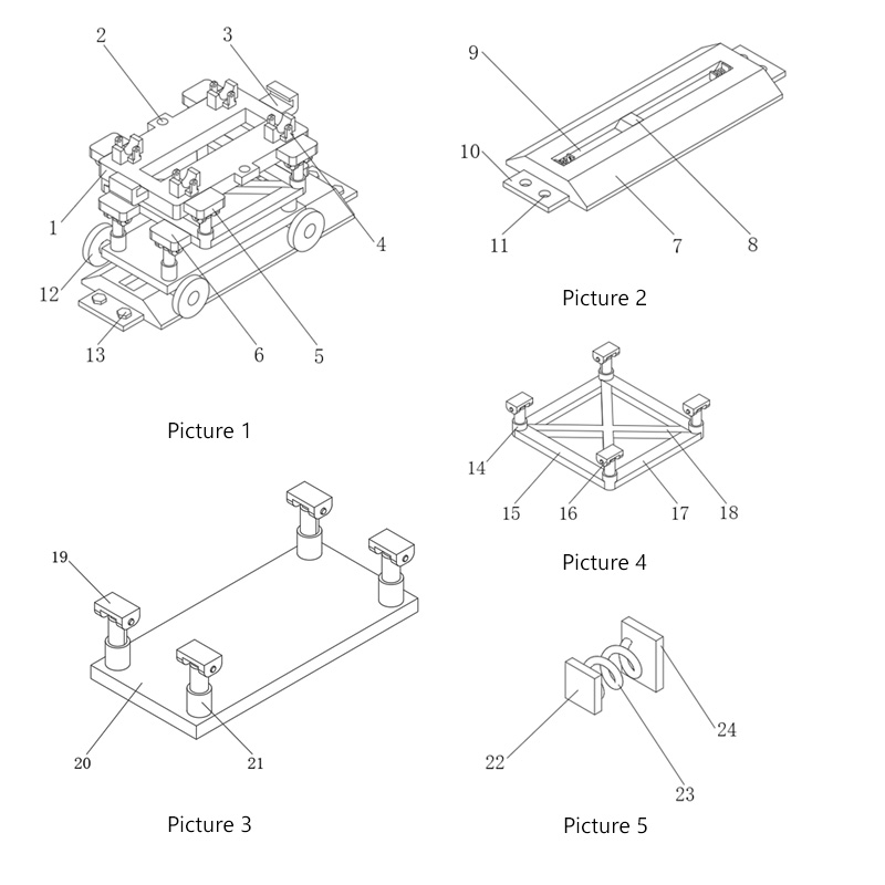
Fig. 1 is a three-dimensional structural schematic diagram of a support plate of the present invention;
Fig. 2 is the three-dimensional structural schematic diagram of the base in the utility model;
Fig. 3 is a three-dimensional structural schematic diagram of a mid-sole plate of the present invention;
Fig. 4 is a three-dimensional structural schematic diagram of a stabilizer in the utility model;
Fig. 5 is a three-dimensional structural schematic diagram of the buffer spring in the utility model.
In the figure: 1. Supporting plate; 2. Fixed through hole; 3. Limiting plate; 4. Wheel fixing frame; 5. First connecting plate; 6. Second connecting plate; 7. Base; 8. Slide block; 9 , chute; 10, positioning plate; 11, threaded through hole; 12, sliding wheel; 13, fixing bolt; 14, first hydraulic rod; 15, fixing plate; 16, first clamping block; 17, stabilization plate; 18 , stabilizer; 19, second block; 20, bottom plate; 21, second hydraulic rod; 22, backing plate; 23, buffer spring; 24, spring plate.
Detailed Description
The technical solutions in the embodiments of the present utility model will be clearly and completely described below with reference to the accompanying drawings in the embodiments of the present utility model. Obviously, the described embodiments are only a part of the embodiments of the present utility model, rather than all the implementations. example. Based on the embodiments of the present invention, all other embodiments obtained by those of ordinary skill in the art without creative work fall within the protection scope of the present invention.
Referring to FIGS. 1 to 5 , in the embodiment of the present utility model, an integrated machine for vehicle sense and belt sense detection includes a support plate 1 . The upper surface of the support plate 1 is fixedly connected with two sets of wheel fixing frames 4 . Two first connecting plates 5 are fixedly connected to the back of the supporting plate 1 , the bottom surface of each first connecting plate 5 is fixedly connected with a first clamping block 16 , and two sets of first hydraulic rods are placed under the supporting plate 1 14. The output end of each group of first hydraulic rods 14 is fixedly connected to the interior of the first block 16, and the outer surfaces of each group of first hydraulic rods 14 are fixedly connected with a fixed plate 15, and the two fixed plates 15 are far away from each other. Two second connecting plates 6 are fixedly connected to one side of each second connecting plate 6, the bottom surface of each second connecting plate 6 is fixedly connected with a second clamping block 19, a bottom plate 20 is placed under the supporting plate 1, and the upper surface of the bottom plate 20 is fixedly connected There are two sets of second hydraulic rods 21 , and the output ends of each set of second hydraulic rods 21 are fixedly connected to the inside of the second clamping block 19 through pins.
A base 7 is placed under the bottom plate 20, a chute 9 is opened inside the base 7, a sliding block 8 is clamped inside the chute 9, and the upper surface of the sliding block 8 is fixedly connected with the bottom surface of the bottom plate 20. The left side and the right side of the base 7 are fixedly connected with the positioning plate 10, which can detect the response speed and effect of the seat belt, and play a role in further improving the detection function of the device. The front of the bottom plate 20 and the back of the bottom plate 20 Both are fixedly connected with two sliding wheels 12, which can drive the device to move, and play the role of moving the device more quickly. The outer surfaces of the two sets of first hydraulic rods 14 are fixedly and fixedly connected with a stabilizer 18, which can stabilize the first hydraulic rod 14. The hydraulic rod 14 plays the role of more stable operation of the first hydraulic rod 14 .
The upper surface of the support plate 1 is provided with two fixing through holes 2, and the left side of the support plate 1 and the right side of the support plate 1 are both fixedly connected to the limit plate 3, which can further fix the test vehicle and play a role in To increase the safety of the test, two stabilizing plates 17 are fixedly connected to the outer surfaces of the two sets of first hydraulic rods 14. The sides of the two stabilizing plates 17 that are close to each other are respectively connected to the front of the stabilizer 18 and the back of the stabilizer 18. The fixed connection can further stabilize the first hydraulic rod 14 and play a role of stronger bearing capacity of the first hydraulic rod 14. The upper surface of each positioning plate 10 is provided with two threaded through holes 11, and each threaded through hole 11 There are fixing bolts 13 threadedly connected to the inside of each fixing bolt 13. The bottom end of each fixing bolt 13 penetrates the threaded through hole 11 and extends to the bottom of the positioning plate 10. After the fixing bolt 13 is screwed into the threaded through hole 11, the base can be 7 is fixed to facilitate the installation by the staff. The inner side wall of the chute 9 is fixedly connected with two spring plates 24, and the side surfaces of the two spring plates 24 that are close to each other are fixedly connected with buffer springs 23. Both ends of the springs 23 that are close to each other are fixedly connected with a backing plate 22 , which can buffer the sliding block 8 when the sliding block 8 slides, so as to protect the sliding block 8 .
The working principle of the utility model is as follows: when in use, firstly connect the first hydraulic rod 14 and the second hydraulic rod 21 with the power supply, and when the vehicle feel needs to be detected, use a crane to move the vehicle to be detected to the support Above the plate 1, and then the vehicle is fixed by the wheel fixing frame 4 to prevent the test vehicle from falling during the test. The power provided by the first hydraulic rod 14 can drive the support plate 1 to swing up and down in the front and rear directions. When the support plate 1 swings, it can drive the test vehicle to swing, and the power provided by the second hydraulic rod 21 can drive the fixed plate 15 to swing up and down in the left and right directions. The test vehicle swings so that it can simulate the feeling of the driver in the vehicle when the vehicle passes through different road conditions, so as to avoid the detection of only one direction of the vehicle, which increases the detection time of the vehicle and reduces the detection efficiency of the vehicle. The problem of the use cost of the inspection machine is increased. When the response speed and effect of the seat belt need to be inspected, the device is quickly pushed to make the sliding wheel 12 rotate. When the sliding block 8 is in contact with the backing plate 22, the device can be quickly stopped. Movement, to simulate the situation of sudden braking, so as to achieve the purpose of detecting the response speed and effect of the seat belt.
The above are only the preferred specific embodiments of the present invention, but the protection scope of the present invention is not limited to this. Equivalent replacement or modification of the new technical solution and its utility model concept shall be included within the protection scope of the present utility model.