Automobile Seat Belt Electronic Tensile Test Device
Summary Of Instruction
The utility model relates to an electronic tension test device for automobile safety belts in the field of tension test devices. The inner bottom end of the working box is provided with a second rotating column, and a rolling belt is arranged between the first rotating column and the second rotating column. It has high accuracy, and the device is simple and easy to operate, which saves the time for staff to assemble and calculate the tension force, and improves the test efficiency. The force value sensor is connected and fixed with the first fixture through the screw hole. High, the performance for repeated use is good, and the service life is long under normal conditions, which avoids the problems of inaccurate testing and inability to transmit tensile force data in time, improves the efficiency of tensile testing, and saves time and effort.
Abstract Drawings
Claim Of Rights
- The electronic tensile test device for automobile seat belts comprises a bottom plate (1) and a box body (21), characterized in that: the box body (21) is arranged on the top of the bottom plate (1), and a working box is arranged on the top of the bottom plate (1). (2), the inner top end of the working box (2) is provided with a first rotating column (5), the inner bottom end of the working box (2) is provided with a second rotating column (6), and the first rotating column A rolling belt (4) is provided between (5) and the second rotating column (6), and the rolling belt (4) is rotatably connected with the first rotating column (5) and the second rotating column (6), and the working A motor (18) is fixedly installed at the bottom of the right side of the box (2) through a fixing plate (17). ) fixed connection, the top of the bottom plate (1) is located at the front end of the working box (2) is provided with a hydraulic cylinder (7), the top of the hydraulic cylinder (7) is fixedly installed with a fixing block (8), the fixing block (8) The rear end is fixedly installed with a moving beam (9), the rear end of the moving beam (9) penetrates the work box (2) and extends to the inside of the work box (2), and the moving beam (9) extends to the work box (2) One end of the inner part is fixedly connected to the surface of the rolling belt (4), a fixing rod (10) is penetrated through the top middle of the moving beam (9), and a force sensor (12) is fixedly installed at the bottom end of the fixing rod (10). A first clamp (13) is fixedly installed at the bottom end of the force sensor (12), and a bottom post (16) is fixedly installed at the bottom end of the bottom plate (1) at the bottom end of the first clamp (13). The bottom post (16) A fixing column (15) is fixedly installed at the top end, and a second clamp (14) is fixedly installed at the top end of the fixing column (15).
- The electronic tension test device for automobile seat belts according to claim 1, characterized in that: the inner wall of the fixing plate (17) is in contact with the motor (18), and the top of the fixing plate (17) is located before and after the motor (18). The end is fixed on the top of the base plate (1) by fixing screws (19).
- The electronic tension test device for automobile seat belts according to claim 1, characterized in that: a limit rod (11) is provided on the top of the outer wall of the fixed rod (10) above the moving beam (9), and the limit rod (11) ) penetrates the fixing rod (10) and extends to the outside of the fixing rod (10).
- The electronic tension test device for automobile seat belts according to claim 1, characterized in that: an opening (3) is provided at the front end of the work box (2).
- The electronic tension test device for automobile seat belts according to claim 1, characterized in that: the first rotating column (5) and the second rotating column (6) are rotatably connected to the inside of the working box (2).
- The electronic tensile test device for automobile seat belts according to claim 1, characterized in that: a box door (23) is fixedly installed on the right side of the front end of the box body (21) through a hinge (22), and the box door ( 23) is movably connected with the front end of the box body (21), a handle (25) is installed on the left side of the front end of the box door (23), and a glass (24) is arranged at the front end of the box door (23).
- The electronic tension test device for automobile seat belts according to claim 1, characterized in that: rollers (20) are installed at the four corners of the lower end of the bottom plate (1), and the upper ends of the rollers (20) are fixed to the bottom plate (1). connect.
Instruction Manual Drawings
Automobile seat belt electronic tensile test device
Technical Field
The utility model relates to the field of tensile testing devices, in particular to an electronic tensile testing device for automobile safety belts.
Background Technique
One of the key instruments for testing the mechanical properties of materials is the tensile testing machine. In the prior art, commonly used tensile testing devices are divided into electronic tensile testing devices and hydraulic tensile testing devices. Controlling the loading can make the testing accuracy, transmission efficiency and maneuverability more advantageous than the hydraulic tensile testing device; but at present, when loading and unloading materials in China, it is usually manual loading and unloading, which consumes more time and manpower.
In the prior art, the pendulum tensile testing machine is generally composed of a loading mechanism, a force measuring mechanism, a recording device, an elongation measuring device, a buffer device and a force transmission mechanism. The steps are complex, the amount of calculation is large, and the accuracy of the test data is not high. Therefore, in order to overcome the above-mentioned defects, how to effectively solve the problems of data accuracy, complicated operation, large amount of calculation, and the danger of the breaking process in the tensile test are urgent problems to be solved by those skilled in the art. Therefore, those skilled in the art provide a vehicle seat belt tension test device to solve the above-mentioned problems in the background art.
Utility Model Content
The purpose of the present utility model is to provide an electronic tension test device for automobile seat belts, so as to solve the problems raised in the above-mentioned background art.
To achieve the above object, the utility model provides the following technical solutions:
The electronic tensile test device for automobile seat belts includes a bottom plate and a box body, the box body is arranged on the top of the bottom plate, a working box is arranged on the top of the bottom plate, and a first rotating column is arranged on the inner top of the working box. The inner bottom end is provided with a second rotating column, a rolling belt is arranged between the first rotating column and the second rotating column, and the rolling belt is rotatably connected with the first rotating column and the second rotating column, and the right side of the working box is A motor is fixedly installed on the side bottom through the fixing plate, the output end of the motor penetrates the working box and is fixedly connected with the second rotating column inside the working box, the top of the bottom plate is located at the front end of the working box and is provided with a hydraulic cylinder, and the top of the hydraulic cylinder is fixed A fixed block is installed, the rear end of the fixed block is fixedly installed with a moving beam, the rear end of the moving beam penetrates the working box and extends to the inside of the working box, and one end of the moving beam extending to the inside of the working box is fixedly connected to the surface of the rolling belt , a fixed rod runs through the middle of the top of the moving beam, a force sensor is fixedly installed at the bottom end of the fixed rod, a first clamp is fixedly installed at the bottom end of the force sensor, and the top of the bottom plate is fixedly installed at the bottom end of the first clamp There is a bottom column, the top of the bottom column is fixedly installed with a fixed column, and the top of the fixed column is fixedly mounted with a second clamp.
As a further solution of the present invention, the inner wall of the fixing plate is in contact with the motor, and the top of the fixing plate is located at the front and rear ends of the motor and is fixedly installed on the top of the bottom plate by fixing screws.
As a further solution of the present invention, the top end of the outer wall of the fixing rod is located above the moving beam, and a limit rod is arranged, and the limit rod penetrates the fixed rod and extends to the outside of the fixed rod.
As a further solution of the present invention, the front end of the working box is provided with an opening.
As a further solution of the present invention, the first rotating column and the second rotating column are rotatably connected with the inside of the working box.
As a further solution of the present invention: a box door is fixedly installed on the right side of the front end of the box body through a hinge hinge, the box door is movably connected with the front end of the box body, a handle is installed on the left side of the front end of the box door, and the box door is installed on the left side of the box body. The front end of the box door is provided with glass.
As a further solution of the present invention, rollers are installed at the four corners of the lower end of the bottom plate, and the upper ends of the rollers are fixedly connected to the bottom plate.
Compared with the prior art, the beneficial effects of the present utility model are:
In the utility model, the safety belt to be tested is clamped by the first clamp and the second clamp, the motor and the hydraulic cylinder are started, the moving beam will move upward to pull the safety belt, the pulling force will have a force value sensor to record and transmit the data, and the electronic tension test will be performed. The combination of the device and the hydraulic tensile test device makes the device more stable, the measured data is highly accurate, and the device is simple and easy to operate, which saves the time for staff to assemble and calculate the tensile force, and improves the test efficiency.
In the utility model, the force value sensor is connected and fixed with the first clamp through the screw hole, the S-type tension pressure sensor has higher precision compared with the same type of products, the performance for repeated use is better, and the service life under normal conditions is long. It avoids the problems of inaccurate testing and inability to transmit tensile data in time, improves the efficiency of tensile testing, and saves time and effort.
Description Of Drawings
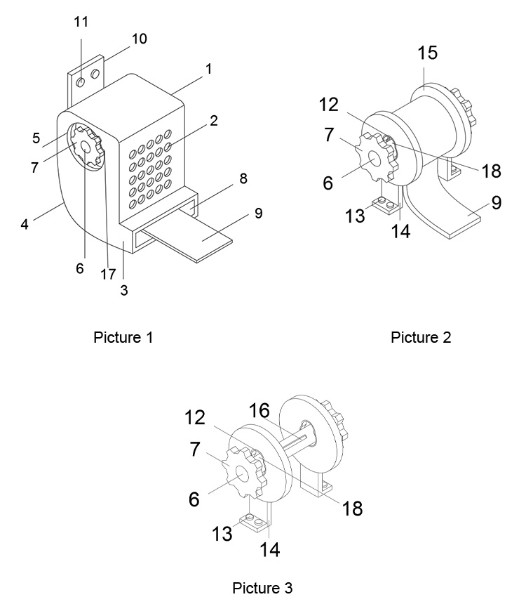
Fig. 1 is the appearance schematic diagram of the utility model;
Fig. 2 is the internal schematic diagram of the box in the utility model;
Fig. 3 is the internal schematic diagram of the working box in the utility model.
In the figure: 1. Bottom plate; 2. Work box; 3. Opening; 4. Rolling belt; 5. First rotating column; 6. Second rotating column; 7. Hydraulic cylinder; 8. Fixed block; 9. Moving beam; 10. Fixing rod; 11. Limiting rod; 12. Force sensor; 13. First fixture; 14. Second fixture; 15. Fixing column; 16. Bottom column; 17. Fixing plate; 18. Motor; 19. Fixing screw; 20, roller; 21, box body; 22, hinge hinge; 23, box door; 24, glass; 25, handle.
Detailed Ways
The technical solutions in the embodiments of the present utility model will be clearly and completely described below with reference to the accompanying drawings in the embodiments of the present utility model. Obviously, the described embodiments are only a part of the embodiments of the present utility model, rather than all the implementations. example. Based on the embodiments of the present invention, all other embodiments obtained by those of ordinary skill in the art without creative work fall within the protection scope of the present invention.
Please refer to FIGS. 1 to 3. In the embodiment of the present invention, the electronic tension test device for automobile seat belts includes a bottom plate 1 and a box body 21. The box body 21 is arranged on the top of the bottom plate 1, and the top of the bottom plate 1 is provided with a work box 2. The work box The inner top end of A rotating column 5 and a second rotating column 6 are rotatably connected, and a motor 18 is fixedly installed at the bottom of the right side of the work box 2 through the fixing plate 17 . The output end of the motor 18 penetrates the working box 2 and is fixed with the second rotating column 6 inside the working box 2 Connection, the top of the bottom plate 1 is located at the front end of the work box 2 is provided with a hydraulic cylinder 7, the top of the hydraulic cylinder 7 is fixedly installed with a fixed block 8, the rear end of the fixed block 8 is fixedly installed with a moving beam 9, and the rear end of the moving beam 9 penetrates through the work box 2 and extends To the inside of the working box 2, the moving beam 9 extends to one end inside the working box 2 and is fixedly connected to the surface of the rolling belt 4. A fixed rod 10 runs through the middle of the top of the moving beam 9. The bottom end of the fixed rod 10 is fixedly installed with a force value sensor 12. The bottom end of the sensor 12 is fixedly installed with a first clamp 13, the top of the bottom plate 1 is located at the bottom end of the first clamp 13 and a bottom column 16 is fixedly installed, the top of the bottom column 16 is fixedly installed with a fixed column 15, and the top of the fixed column 15 is fixedly installed with a second clamp 14.
The inner wall of the fixing plate 17 is in contact with the motor 18, and the top of the fixing plate 17 is located at the front and rear ends of the motor 18 and is fixedly installed on the top of the base plate 1 by fixing screws 19. During use, the motor 18 is fixed by the fixing plate 17 and the fixing screws 19. The top of the outer wall of the rod 10 is located above the moving beam 9 and a limit rod 11 is provided. The limit rod 11 penetrates the fixed rod 10 and extends to the outside of the fixed rod 10. When in use, the fixed rod 10 is fixed on the moving beam 9 through the limit rod 11. , the front end of the work box 2 is provided with an opening 3. When in use, the moving beam 9 is moved upward through the opening 3 and the hydraulic cylinder 7, and the first rotating column 5 and the second rotating column 6 are rotatably connected to the inside of the working box 2. The motor 18 drives the second rotating column 6 to rotate, the second rotating column 6 drives the rolling belt 4 to rotate, and the rolling belt 4 drives the first rotating column 5 to rotate. The box door 23 is movably connected with the front end of the box body 21, a handle 25 is installed on the left side of the front end of the box door 23, and a glass 24 is arranged at the front end of the box door 23. When in use, the box is opened through the handle 25 on the box door 23 set on the box body 21. The door 23 and the four corners of the lower end of the bottom plate 1 are equipped with rollers 20, and the upper ends of the rollers 20 are fixedly connected with the bottom plate 1. When in use, the rollers 20 installed at the four corners of the bottom of the bottom plate 1 are used. This design solves the problem of device movement.
The working principle of the utility model is as follows: push the device to the place where the operation needs to be performed, connect the power supply, open the box door 23 during operation, clamp the top end of the safety belt on the bottom end of the first clamp 13, and clamp the bottom end of the safety belt on the second The top of the clamp 14, close the box door 23, start the motor 18, the rotation of the output shaft of the motor 18 drives the second rotating column 6 inside the work box 2 to rotate, the second rotating column 6 rotates to drive the rolling belt 4 to rotate, and the rolling belt 4 rotates to drive the first rotating The rotating column 5 rotates, starts the hydraulic cylinder 7, the output end of the hydraulic cylinder 7 moves upward, pushes the moving beam 9 to move upward, pulls the seat belt, and observes the pulling condition of the seat belt through the glass 24 on the box door 23. The pulling force is converted into data and transmitted to the computer for people to use the data. The box door 23 is opened through the handle 25 to facilitate the cleaning of the inside of the box body 21. The box door 23 is opened regularly, and the fixing screw 19 and the fixing plate The motor 18 in the box body 21 is maintained, and the rollers 20 installed at the four corners of the bottom plate 1 are convenient for the operation of the mobile device.
The above are only the preferred specific embodiments of the present invention, but the protection scope of the present invention is not limited to this. Equivalent replacement or modification of the new technical solution and its utility model concept shall be included within the protection scope of the present utility model.

Automobile Seat Belt Electronic Tensile Test Device