Car Seat Belt Retractor Coil Spring Stop Structure
Summary Of Instruction
The utility model discloses a coil spring stop structure of an automobile seat belt retractor in the field of auto parts, which comprises a body, a casing is mounted on the outer side of the body, a plurality of ventilation holes are arranged on the front end wall of the casing, a safety belt pipe is arranged at the lower end of the casing, and a safety belt is arranged at the lower end of the casing. The front end of the pipe is provided with a safety belt outlet, the left end of the casing is provided with a hollow hole, the side end of the hollow hole is provided with a groove, the rear wall of the casing is provided with a first mounting seat, and the front end of the first mounting seat is mounted with two first nuts. There are two second mounting seats installed inside the main body. Through the installation of the plastic ring in the groove of the reeling shaft, the reeling shaft will not be worn during long-term rewinding work, and the reeling shaft and baffle are maintained, which effectively avoids the need for rewinding. Damage to the reel and baffle, and avoid direct contact between the reel and baffle to cause rust; and through the setting of multiple ventilation holes on the side of the casing, the air inside the rewinder is circulated, avoiding moisture in the reel, and effectively Moisture-proof, maintains the winder, and improves the practicability of the winder.
Claim Of Rights
- The coil spring stop structure of an automobile seat belt retractor includes a main body (1), characterized in that: an outer casing (4) is installed on the outer side of the main body (1), and a plurality of ventilation holes are provided on the front end wall of the outer casing (4). (2), the lower end of the outer shell (4) is provided with a seat belt conduit (3), the front end of the seat belt conduit (3) is provided with a seat belt outlet (8), and the left end of the outer shell (4) is provided with a hollow out A hole (5), a groove (17) is provided at the side end of the hollow hole (5), a first mounting seat (10) is mounted on the rear end wall of the housing (4), and the first mounting seat (10) Two first nuts (11) are mounted on the front end, two second mounting seats (14) are mounted inside the body (1), and two second mounting seats (14) are mounted on the upper ends of the two second mounting seats (14). A nut (13), a baffle plate (15) is installed on the upper ends of the two second mounting seats (14), and a reeling shaft clamping groove (18) is provided inside the two baffle plates (15). Plastic rings (12) are installed in the reeling shaft clamping grooves (18), rewinding shafts (6) are installed inside the two plastic rings (12), and safety belt clips are arranged at the side ends of the reeling shafts (6). A slot (16), a safety belt (9) is installed inside the safety belt clip slot (16), and gears (7) are installed on both sides of the take-up shaft (6).
- The car seat belt retractor coil spring stop structure according to claim 1, characterized in that: the seat belt (9) is fixedly connected to the seat belt clip slot (16), and the seat belt (9) passes through The seat belt slot (16) is rotatably connected with the take-up shaft (6).
- The coil spring stop structure of an automobile seat belt retractor according to claim 1, characterized in that: the reeling shaft clamping groove (18) is in communication with the baffle plate (15), and the plastic ring (12) is connected to the interior of the baffle plate (15). The baffle (15) is fixedly connected.
- The coil spring stop structure of an automobile seat belt retractor according to claim 1, characterized in that: the reeling shaft (6) is fixedly connected to the gear (7), and the groove (17) is connected to the hollow ( 5) Fixed connection, and the hollow hole (5) communicates with the interior of the body (1).
- The coil spring stop structure of an automobile seat belt retractor according to claim 1, characterized in that: the seat belt pipe (3) is communicated with the inside of the body (1), and the seat belt outlet (8) is connected to the safety belt With pipe (3) internal communication.
- The coil spring stop structure of an automobile seat belt retractor according to claim 1, characterized in that: the second mounting seat (14) is fixedly connected to the main body (1) through a second nut (13), and the The second mounting seat (14) is fixedly connected with the baffle plate (15).
- The coil spring stop structure of an automobile seat belt retractor according to claim 1, characterized in that: the plurality of ventilation holes (2) are communicated with the inside of the main body (1), and the hollow holes (5) are connected to the main body (1). (1) Internal connection.
Car Seat Belt Retractor Coil Spring Stop Structure
Technical Field
The utility model relates to the field of auto parts, in particular to a coil spring stop structure of an automobile seat belt retractor.
Background Technique
The retractor refers to the retractor with the emergency locking function, which is the core component of the car seat belt. The seat belt retractor is characterized in that the part that senses the acceleration of the webbing is composed of a circular reeling shaft and at least one ratchet fixedly installed at the end of the shaft, and the circular reeling shaft can be movably passed through the reeling belt. In the oval shaft holes of the main board on both sides of the bin, an inner ratchet is arranged on the oblique upper part of the oval shaft hole on the inner side of the main board, which forms a locking part with the ratchet wheel.
In the prior art, when the retractor is in use, since the safety belt is reeled by the rewinding shaft, and the reeling shaft often rubs against the baffle plate, after long-term use, the reeling shaft is usually worn out after friction. And it is easy to rust, which affects the use of the seat belt and reduces the practicability of the winding shaft; the existing winder will be enclosed in a sealed space, and the winder will be airtight. When the air conditioner is turned on in the car, the winder will produce Fog water makes the inside of the winder wet, and it is not easy to dry, which makes the inside of the winder easy to rust.
Utility Model Content
The purpose of the present invention is to provide a coil spring stop structure for an automobile seat belt retractor, so as to solve the problems raised in the above-mentioned background technology.
To achieve the above object, the utility model provides the following technical solutions:
The coil spring stop structure of an automobile seat belt retractor includes a body, a casing is installed on the outside of the body, a plurality of ventilation holes are arranged on the front end wall of the casing, and a seat belt pipe is arranged at the lower end of the casing, and the seat belt pipe The front end is provided with a safety belt outlet, the left end of the casing is provided with a hollow hole, the side end of the hollow hole is provided with a groove, the rear end wall of the casing is provided with a first mounting seat, and the front end of the first mounting seat is mounted There are two first nuts, two second mounting seats are installed inside the body, two second nuts are installed on the upper ends of the two second mounting seats, and two second mounting seats are installed on the upper ends of the two second mounting seats. baffles, both of the baffles are provided with a reeling shaft slot, and a plastic ring is installed in the two reeling shaft slots, and a rewinding shaft is installed inside the two plastic rings, and the reeling shaft side The end is provided with a safety belt clip slot, a safety belt is installed inside the safety belt clip slot, and gears are installed on both sides of the take-up shaft.
As a further solution of the present invention, the safety belt is fixedly connected with the safety belt clipping slot, and the safety belt is rotatably connected with the take-up shaft through the safety belt clipping slot.
As a further solution of the present invention, the reeling shaft clamping groove is communicated with the interior of the baffle, and the plastic ring is fixedly connected to the baffle.
As a further solution of the present invention, the winding shaft is fixedly connected with the gear, and the groove is fixedly connected with the hollowed-out hole, and the hollowed-out hole is communicated with the inside of the body.
As a further solution of the present invention, the seat belt duct is communicated with the inside of the body, and the seat belt outlet is communicated with the inside of the seat belt duct.
As a further solution of the present invention, the second mounting seat is fixedly connected to the body through a second nut, and the second mounting seat is fixedly connected to the baffle plate.
As a further solution of the present invention, a plurality of the ventilation holes are communicated with the inside of the body, and the hollow holes are communicated with the interior of the body.
Compared with the prior art, the beneficial effects of the present utility model are:
In the utility model, through the installation of the plastic ring in the clamping groove of the reeling shaft, the reeling shaft will not be worn during long-term rewinding work, which is beneficial to the maintenance of the reeling shaft and the baffle plate, and effectively avoids the need for the reeling shaft and the baffle plate. and avoid direct contact between the rewinding shaft and the baffle to cause rust; and through the arrangement of multiple ventilation holes on the side of the casing, the air inside the rewinder is circulated, avoiding moisture in the rewinder, and effectively preventing moisture, which is beneficial to The maintenance of the winder improves the practicability of the winder.
Description Of Drawings
Fig. 1 is the structural representation of the utility model;
Fig. 2 is the structural representation of the safety belt in the utility model;
FIG. 3 is a schematic structural diagram of a take-up reel in the utility model.
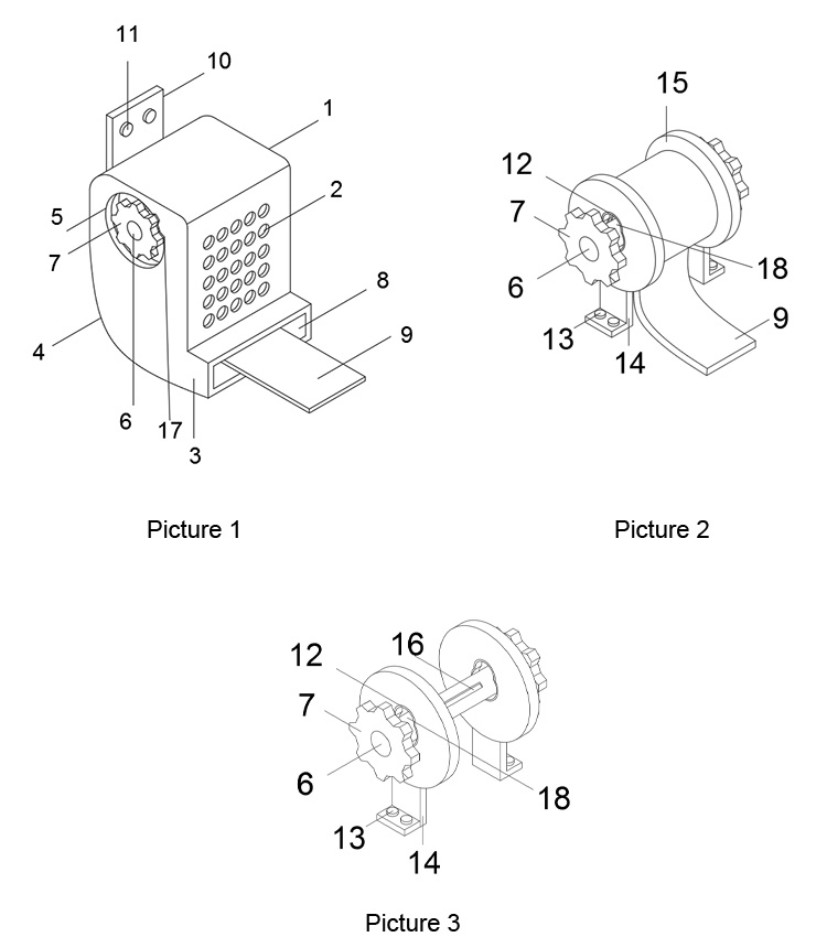
In the picture: 1. Main body; 2. Ventilation hole; 3. Seat belt pipe; 4. Shell; 5. Hollow hole; 6. Rewinding shaft; 7. Gear; 8. Seat belt outlet; 9. Seat belt; A mounting seat; 11, the first nut; 12, the plastic ring; 13, the second nut; 14, the second mounting seat; 15, the baffle; 16, the seat belt slot; 17, the groove; groove.
Detailed Ways
The technical solutions in the embodiments of the present utility model will be clearly and completely described below with reference to the accompanying drawings in the embodiments of the present utility model. Obviously, the described embodiments are only a part of the embodiments of the present utility model, rather than all the implementations. example. Based on the embodiments of the present invention, all other embodiments obtained by persons of ordinary skill in the art without creative work shall fall within the protection scope of the present invention.
Please refer to FIGS. 1 to 3. In the embodiment of the present utility model, the coil spring stop structure of the car seat belt retractor includes a main body 1, an outer casing 4 is mounted on the outer side of the main body 1, and the front end wall of the outer casing 4 is provided with a plurality of ventilation holes 2, The lower end of the shell 4 is provided with a seat belt pipe 3, the front end of the seat belt pipe 3 is provided with a seat belt outlet 8, the left end of the shell 4 is provided with a hollow hole 5, the side end of the hollow hole 5 is provided with a groove 17, and the rear end wall of the shell 4 is installed There is a first mounting seat 10 , two first nuts 11 are mounted on the front end of the first mounting seat 10 , two second mounting seats 14 are mounted inside the main body 1 , and two second mounting seats 14 are mounted on the upper ends of the two second mounting seats 14 . The nut 13, the upper ends of the two second mounting seats 14 are installed with baffles 15, the two baffles 15 are provided with reeling shaft clamping grooves 18, and the two reeling shaft clamping grooves 18 are both installed with plastic rings 12, two Inside the plastic ring 12 is installed a rewinding shaft 6 , the side end of the reeling shaft 6 is provided with a seat belt slot 16 , the seat belt slot 16 is fitted with a safety belt 9 , and both sides of the rewinding shaft 6 are installed with gears 7 .
The safety belt 9 is fixedly connected with the safety belt clip slot 16 , and the safety belt 9 is rotatably connected with the take-up reel 6 through the safety belt clip slot 16 . When in use, when the user pulls out the safety belt 9 , the take-up reel 6 rotates. The extension and retraction of the seat belt 9 makes the use of the seat belt 9 more convenient.
The reeling shaft slot 18 is communicated with the baffle 15, and the plastic ring 12 is fixedly connected with the baffle 15. When in use, the reeling shaft 6 in the reeling shaft slot 18 will not be worn during rotation, so as to avoid damage to the reeling shaft 6 .
The take-up shaft 6 is fixedly connected with the gear 7, and the groove 17 is fixedly connected with the hollow hole 5, and the hollow hole 5 is communicated with the interior of the main body 1. During use, when the safety belt 9 is pulled out too fast, the force of the safety belt 9 The reel 6 will be lifted and stuck above the reel slot 18 , so that the gear 7 will be stuck in the slot 17 , and the safety belt 9 cannot be pulled out, which is beneficial to the maintenance of the safety belt 9 .
The seat belt duct 3 is communicated with the interior of the body 1, and the seat belt outlet 8 is communicated with the interior of the seat belt duct 3. When in use, the seat belt 9 is pulled out from the seat belt outlet 8 by the take-up reel 6 through the seat belt duct 3.
The second mounting seat 14 is fixedly connected to the body 1 through the second nut 13, and the second mounting seat 14 is fixedly connected to the baffle 15. When in use, the baffle 15 is fixed in the body 1 through the second mounting seat 14, so that the safety belt 9. The rewinding device is fixed inside the main body 1, which makes the retractor more stable and improves the quality of the retractor.
The plurality of ventilation holes 2 are communicated with the interior of the body 1, and the hollow holes 5 are communicated with the interior of the body 1. When in use, the safety belt 9 is wound inside the body 1 through the winding shaft 6, and the ventilation holes 2 allow the air in the body 1 to circulate, avoiding the 1 is damp and rusted.
The working principle of the present invention is as follows: firstly, the second mounting seat 14 is fixed inside the main body 1 by the second nut 13 , and one end of the safety belt 9 is fixed with the safety belt slot 16 at the side end of the take-up shaft 6 to prevent the safety belt 9 from falling off. , fix the first mounting seat 10 by the first nut 11 in the required position, after the installation is completed, the seat belt 9 can be pulled and pulled, pick up the seat belt 9 and pull it down, the speed should not be too fast, when the speed of pulling the seat belt 9 When it is too fast, the rewinding shaft 6 at the end of the safety belt 9 will be brought up, so that it is locked into the upper end of the reeling shaft slot 18 in the baffle 15. Since the gear 7 is fixedly connected with the reeling shaft 6, after the reeling shaft 6 is lifted, The gear 7 will also be lifted and inserted into the groove 17 at the side end of the hollow hole 5, and the reel 6 will be fixed so that it cannot rotate, then the seat belt 9 cannot be pulled out continuously. After loosening the seat belt 9, the reel 6 and The gear 7 can be restored to its original position, and the seat belt 9 can be pulled out at a slow speed. The seat belt 9 can still be used normally, and a plurality of ventilation holes 2 are installed on the side end of the outer casing 4, so that the air inside the main body 1 can circulate, which is conducive to the winding up. maintenance of the appliance.
The above are only the preferred specific embodiments of the present invention, but the protection scope of the present invention is not limited to this. Equivalent replacement or modification of the new technical solution and its utility model concept shall be included within the protection scope of the present utility model.
Car Seat Belt Retractor Coil Spring Stop Structure
 Static Seat Belt
 Universal 2-Point Seat Belt
 Universal 3-Point Seat Belt
 Baby Seat Fittings / Holder
 Seat Belt Extender
 Wheelchair Seatbelt
 Racing Seat Belt
 Seat Belt Tongues/Buckles
 Anchorage Rings
 Anchorage Plate
 Seat Belt Adjuster