Summary Of Instruction
The utility model discloses a noise-suppressing automobile safety belt retractor in the field of automobile accessories. The retractor includes a mounting seat. The mounting seat is provided with a plurality of mounting holes. Cover, the left end of the side cover is equipped with an outer cover, the right end of the winder presses the left and right shells, the front of the top of the winder is installed with an outlet frame, the outlet frame is provided with a cavity, and the left and right ends of the cavity are provided with multiple movable cavities. Connecting plates are installed in the multiple movable cavities, springs are installed on the outer end walls of the multiple connecting plates, and sliding rollers are installed on the inner side of the multiple connecting plates, and the multiple sliding rollers are rotatably connected with the inner end wall of the movable cavity. When the safety belt is taken out from the winder, the sliding roller can improve the sliding of the safety belt and eliminate the friction, which is beneficial to the maintenance of the safety belt, and the sliding roller can move back and forth through the action of the spring, which can avoid the safety belt The friction with the exit of the winder produces noise, which is beneficial to improve its functionality and practicability.
Rights Request
- The noise-suppressing car seat belt retractor includes a mounting seat (1), characterized in that: the mounting seat (1) is provided with a plurality of mounting holes (11), and the front end of the mounting seat (1) is equipped with a retractor A side cover (21) is installed on the left end wall of the winder (2), a cover (3) is installed on the left end of the side cover (21), and the right end of the winder (2) is pressed left and right A housing (4), an outlet frame (5) is installed at the front of the top end of the winder (2), the outlet frame (5) is provided with a cavity (51), the left and right ends of the cavity (51) Each wall is provided with a plurality of movable cavities (52), a connecting plate (53) is installed in the plurality of movable cavities (52), and a spring (54) is installed on the outer end wall of the plurality of connecting plates (53) , And a sliding roller (55) is installed on the inner side of the plurality of connecting plates (53), and a safety belt (6) is arranged between the plurality of sliding rollers (55).
- The noise-suppressing automobile seat belt retractor according to claim 1, characterized in that: the retractor (2) is fixedly connected to the mounting seat (1), and the mounting seat (1) is installed by a plurality of The holes (11) and bolts are fitted on the car.
- The noise-suppressing automobile seat belt retractor according to claim 1, characterized in that: the outer cover (3) is installed on the side cover (21) through a fixing seat (31), and the outer cover (3) is inside Stop ratchet.
- The car seat belt retractor for suppressing noise according to claim 1, characterized in that: the front part of the upper end of the retractor (2) is provided with a through hole, and the through hole is connected to the outlet frame (5). The cavity size is uniform.
- The noise-suppressing automobile seat belt retractor according to claim 1, characterized in that: the outlet frame (5) is installed on the upper end wall of the retractor (2) by fixing bolts on both sides of the outlet frame (5), and the outlet frame (5) Fixedly connect with the top wall of the winder (2).
- The noise-suppressing automobile seat belt retractor according to claim 1, characterized in that: a plurality of said sliding rollers (55) are all installed in the movable cavity (52) through bearings, and a plurality of said sliding rollers ( 55) are all rotatably connected with the inner end wall of the movable cavity (52).
- The noise-suppressing automobile seat belt retractor according to claim 1, characterized in that: the rotating shafts at both ends of the plurality of sliding rollers (55) are in close contact with the connecting plate (53), and the connecting plate (53) ) Match the internal dimensions of the movable cavity 52.
Manual
Car seat belt retractor capable of suppressing noise
Technical field
The utility model relates to the field of auto parts, in particular to a car seat belt retractor for suppressing noise.
Background technique
The retractor is the core component of the car seat belt, accounting for 60%-95% of the cost of the seat belt. The seat belt retractor for the car seat is characterized in that the component that senses the acceleration of the webbing is composed of a circular reel shaft and at least one fixed The ratchet wheel is installed at the end of the shaft. The circular take-up shaft can movably pass through the elliptical shaft holes of the main board on both sides of the take-up bin, and an internal ratchet is provided obliquely above the elliptical shaft hole on the inner side of the main board, which forms a lock with the ratchet. Halt parts.
In the existing technology, when the car seat belt retractor is used, there is no protective noise reduction measure at the seat belt exit. When the seat belt is pulled out of the retractor, the friction between the seat belt and the retractor exit produces noise, and the length is long. Time friction can easily lead to damage to the seat belt and affect its use, leading to a decrease in its practicability and functionality.
Utility model content
The purpose of the present invention is to provide a noise-suppressing automobile seat belt retractor to solve the problems raised in the background art.
In order to achieve the above objectives, the present utility model provides the following technical solutions:
A noise-suppressing car seat belt retractor includes a mounting seat, a plurality of mounting holes are provided on the mounting seat, a winder is installed at the front end of the mounting seat, and a side cover is installed on the left end wall of the winder, so An outer cover is installed at the left end of the side cover, the right end of the rewinder presses the left and right housings, the front of the top of the rewinder is installed with an outlet frame, and the outlet frame is provided with a cavity. A plurality of movable cavities are provided, and connecting plates are installed in the plurality of movable cavities, springs are installed on the outer end walls of the plurality of connecting plates, and sliding rollers are installed on the inner sides of the plurality of connecting plates. A safety belt is arranged between the sliding rollers.
As a further solution of the present invention: the winder is fixedly connected to the mounting base, and the mounting base is installed on the automobile through the cooperation of a plurality of mounting holes and bolts.
As a further solution of the present invention: The outer cover is installed on the side cover through a fixing seat, and the inner cover is a stop ratchet. When in use, the inner stop ratchet cover is stopped by the outer cover, and dust enters the inside. Effectively improve its stability in use.
As a further solution of the present invention: the front part of the upper end of the winder is provided with a through hole, and the through hole is the same size as the cavity on the outlet frame.
As a further solution of the present invention: the outlet frame is installed on the upper end wall of the winder by fixing bolts on both sides, and the outlet frame is fixedly connected to the top wall of the winder. When in use, the internal safety belt of the winder Export from the export box for use.
As a further solution of the present invention: a plurality of said sliding rollers are all installed in the movable cavity through bearings, and a plurality of said sliding rollers are all rotatably connected with the inner end wall of the movable cavity, when the safety belt is taken out from the winder At the same time, the sliding roller can improve the slippage of the seat belt and eliminate the friction force, which is beneficial to the maintenance of the seat belt.
As a further solution of the present invention: the rotating shafts at both ends of the plurality of sliding rollers are in close contact with the connecting plate, and the connecting plate matches the internal size of the movable cavity. When the safety belt is pulled out, the sliding roller can pass The action of the spring moves back and forth, which can avoid the friction between the safety belt and the exit of the winder to produce noise.
Compared with the prior art, the beneficial effects of the utility model are:
In the utility model, a plurality of sliding rollers are all installed in the movable cavity through bearings, and the plurality of sliding rollers are all rotatably connected with the inner end wall of the movable cavity. When the safety belt is led out from the winder, the sliding rollers can improve safety The sliding of the belt pulls out to eliminate friction, which is beneficial to the maintenance of the seat belt, and the sliding roller can move back and forth through the action of the spring, which can avoid the friction between the seat belt and the winder exit and generate noise, which is beneficial to improve its functionality And practicality.
Description of the drawings
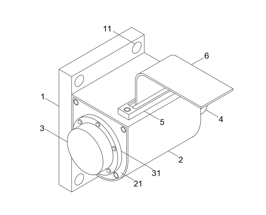
Figure 1 is a schematic diagram of the structure of the utility model;
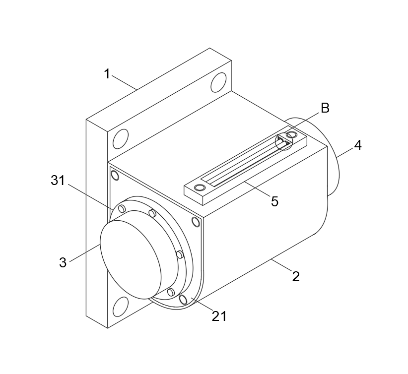
Figure 2 is a schematic diagram of the structure of the exit frame in the utility model;
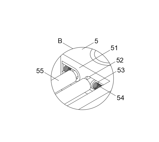
Figure 3 is an enlarged view of B in Figure 2 of the utility model.
In the figure: 1. Mounting seat; 11. Mounting hole; 2. Rewinder; 21. Side cover; 3. Cover; 31. Fixing seat; 4. Shell; 5. Outlet frame; 51. Cavity; 52. Activity Cavity; 53, connecting plate; 54, spring; 55, sliding roller; 6, safety belt.
Detailed Description
The following will clearly and completely describe the technical solutions in the embodiments of the present utility model in conjunction with the accompanying drawings in the embodiments of the present utility model. Obviously, the described embodiments are only a part of the embodiments of the present utility model, rather than all implementations. example. Based on the embodiments of the present utility model, all other embodiments obtained by those of ordinary skill in the art without creative work shall fall within the protection scope of the present utility model.
Please refer to Figures 1 to 3. In the embodiment of the present utility model, the noise-suppressing car seat belt retractor includes a mounting base 1. The mounting base 1 is provided with a plurality of mounting holes 11, and the front end of the mounting base 1 is equipped with a retractor 2. A side cover 21 is installed on the left end wall of the winder 2; a cover 3 is installed on the left end of the side cover 21; A cavity 51 is provided. The left and right ends of the cavity 51 are provided with a plurality of movable cavities 52. The plurality of movable cavities 52 are equipped with connecting plates 53. The outer end walls of the plurality of connecting plates 53 are all equipped with springs 54. Slide rollers 55 are installed inside the multiple connecting plates 53, and a safety belt 6 is provided between the multiple slide rollers 55.
Among them, the winder 2 is fixedly connected to the mounting base 1, and the mounting base 1 is installed on the automobile through the cooperation of a plurality of mounting holes 11 and bolts.
The outer cover 3 is installed on the side cover 21 through the fixing seat 31, and the inner cover 3 has a stop ratchet. When in use, the inner cover 3 is used to stop the ratchet cover to put dust into the inside, which effectively improves its stability in use.
The front part of the upper end of the winder 2 is provided with a through hole, and the through hole is the same size as the cavity on the outlet frame 5.
The outlet frame 5 is installed on the upper end wall of the rewinder 2 by fixing bolts on both sides, and the outlet frame 5 is fixedly connected with the top wall of the rewinder 2. When in use, the internal safety belt 6 of the rewinder 2 is exported from the outlet frame 5 for use .
The multiple sliding rollers 55 are all mounted in the movable cavity 52 through bearings, and the multiple sliding rollers 55 are all rotatably connected with the inner end wall of the movable cavity 52. When the safety belt 6 is led out from the winder 2, the sliding roller 55 can The sliding of the seat belt 6 is improved, and friction is eliminated, which is beneficial to the maintenance of the seat belt 6.
The rotating shafts at both ends of the multiple sliding rollers 55 are in close contact with the connecting plate 53, and the connecting plate 53 matches the internal size of the movable cavity 52. When the safety belt 6 is pulled out, the sliding roller 55 can move back and forth through the action of the spring 54. It can avoid the friction between the safety belt 6 and the exit of the winder 2 to generate noise.
The working principle of the utility model is: the mounting base 1 is installed on the car through the cooperation of multiple mounting holes 11 and bolts, and the outer cover 3 is mounted on the side cover 21 through the fixing base 31, and the inner stop ratchet of the outer cover 3, when in use, The ratchet shield is locked inside the outer cover 3 to place dust into it, which effectively improves its stability in use. The outlet frame 5 is installed on the upper end wall of the winder 2 by fixing bolts on both sides, and the outlet frame 5 is connected to the winder The top wall of the winder 2 is fixedly connected. When in use, the internal safety belt 6 of the winder 2 is taken out from the exit frame 5 for use. A plurality of sliding rollers 55 are installed in the movable cavity 52 through bearings, and the plurality of sliding rollers 55 are all movable with The inner end wall of the cavity 52 is connected in rotation. When the seat belt 6 is drawn out of the winder 2, the sliding roller 55 can improve the sliding performance of the seat belt 6 and eliminate friction, which is beneficial to the maintenance of the seat belt 6. The rotating shafts at both ends of each sliding roller 55 are in close contact with the connecting plate 53, and the connecting plate 53 matches the internal size of the movable cavity 52. When the safety belt 6 is pulled out, the sliding roller 55 can move back and forth through the action of the spring 54. Avoid friction between the safety belt 6 and the exit of the winder 2 to generate noise.
The above are only the preferred specific embodiments of the present utility model, but the protection scope of the present utility model is not limited to this. Anyone familiar with the technical field within the technical scope disclosed in the present utility model, according to the present utility model The technical solutions of the new type and the concept of the utility model are equivalently replaced or changed, which shall be covered by the scope of protection of the utility model.

Picture 1
Picture 2
Picture 3
 Static Seat Belt
 Universal 2-Point Seat Belt
 Universal 3-Point Seat Belt
 Baby Seat Fittings / Holder
 Seat Belt Extender
 Wheelchair Seatbelt
 Racing Seat Belt
 Seat Belt Tongues/Buckles
 Anchorage Rings
 Anchorage Plate
 Seat Belt Adjuster