Noise-Suppressing Car Eeat Belt Retractor
Technical field
The utility model relates to the field of auto parts, in particular to a car seat belt retractor for suppressing noise.
Background technique
The retractor is the core component of the car seat belt, accounting for 60%-95% of the cost of the seat belt. The car seat belt retractor is characterized by a component that senses the acceleration of the webbing and is fixed by a circular reel shaft and at least one It consists of a ratchet mounted on the end of the shaft. The circular reeling shaft movably passes through the oval shaft holes of the main board on both sides of the reeling bin, and an inner ratchet is provided on the obliquely above the oval shaft hole inside the main board, which forms a lock with the ratchet wheel. stop parts.
In the prior art, when the car seat belt retractor is in use, there is no protection and noise reduction measures at the exit of the seat belt. Time friction can easily lead to damage to the seat belt, which affects the use, resulting in a reduction in its practicability and functionality.
Utility model content
The purpose of the present utility model is to provide a car seat belt retractor that suppresses noise, so as to solve the problems raised in the above-mentioned background art.
To achieve the above object, the utility model provides the following technical solutions:
A noise-suppressing car seat belt retractor includes a mounting seat, the mounting seat is provided with a plurality of mounting holes, a retractor is mounted on the front end of the mounting seat, and a side cover is mounted on the left end wall of the retractor, so the A cover is installed at the left end of the side cover, the right end of the winder is pressed against the left and right casings, an outlet frame is installed at the front of the top end of the winder, and a cavity is provided on the outlet frame, and the walls at the left and right ends of the cavity are There are multiple movable cavities, connecting plates are installed in the multiple movable cavities, springs are installed on the outer end walls of the connecting plates, and sliding rollers are installed on the inner sides of the connecting plates. A safety belt is provided between the sliding rollers.
As a further solution of the present invention, the winder is fixedly connected with the mounting seat, and the mounting seat is mounted on the automobile through the cooperation of a plurality of mounting holes and bolts.
As a further solution of the present utility model: the outer cover is installed on the side cover through the fixing seat, and the inside of the outer cover stops the ratchet wheel. When in use, the inner stopper ratchet is covered by the outer cover, and dust is placed into the inside of the outer cover. Effectively improve its use stability.
As a further solution of the present invention, a through hole is provided at the front of the upper end of the winder, and the size of the through hole is the same as that of the cavity on the outlet frame.
As a further scheme of the present invention: the outlet frame is installed on the upper end wall of the winder through the fixing bolts on both sides, and the outlet frame is fixedly connected to the top wall of the winder. When in use, the inner safety belt of the winder Export from the export box to use.
As a further solution of the present utility model: a plurality of the sliding rollers are installed in the movable cavity through bearings, and the plurality of sliding rollers are rotatably connected with the inner end wall of the movable cavity, and when the safety belt is led out from the winder When the sliding roller is used, the sliding property of the seat belt can be improved, the friction force can be eliminated, and the maintenance of the seat belt can be facilitated.
As a further solution of the present invention: the rotating shafts at both ends of the plurality of sliding rollers are in close contact with the connecting plates, and the connecting plates are matched with the internal dimensions of the movable cavity. When the safety belt is pulled out, the sliding rollers can pass through The action of the spring moves back and forth, which can avoid the friction between the seat belt and the outlet of the retractor to generate noise.
Compared with the prior art, the beneficial effects of the present utility model are:
In the utility model, a plurality of sliding rollers are installed in the movable cavity through bearings, and the plurality of sliding rollers are all rotatably connected with the inner end wall of the movable cavity. When the safety belt is drawn out from the winder, the sliding rollers can improve the safety The sliding of the belt pulls out, eliminates friction, and is beneficial to the maintenance of the seat belt, and the sliding roller can move forward and backward through the action of the spring, which can avoid the friction between the seat belt and the outlet of the winder and generate noise, which is beneficial to improve its functionality. and practicality.
Description of drawings
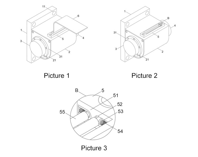
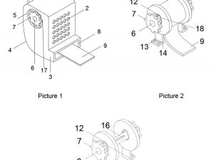
Fig. 1 is the structural representation of the utility model;
Fig. 2 is the structural representation of the outlet frame in the utility model;
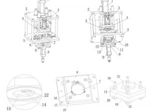
FIG. 3 is an enlarged view of B in FIG. 2 of the utility model.
In the figure: 1. Mounting seat; 11. Mounting hole; 2. Rewinder; 21. Side cover; 3. Cover; 31. Fixed seat; 4. Shell; 5. Outlet frame; 51. Cavity; 52. Movement Cavity; 53, connecting plate; 54, spring; 55, sliding roller; 6, safety belt.
Detailed description
The technical solutions in the embodiments of the present utility model will be clearly and completely described below with reference to the accompanying drawings in the embodiments of the present utility model. Obviously, the described embodiments are only a part of the embodiments of the present utility model, rather than all the implementations. example. Based on the embodiments of the present invention, all other embodiments obtained by those of ordinary skill in the art without creative work fall within the protection scope of the present invention.
Referring to FIGS. 1 to 3 , in the embodiment of the present invention, the noise-suppressing automobile seat belt retractor includes a mounting seat 1 , a plurality of mounting holes 11 are provided on the mounting seat 1 , and a retractor is installed at the front end of the mounting seat 1 2. A side cover 21 is installed on the left end wall of the winder 2, a cover 3 is installed on the left end of the side cover 21, the right end of the winder 2 is pressed against the left and right casings 4, and an outlet frame 5 is installed at the front of the top of the winder 2. A cavity 51 is provided, the left and right end walls of the cavity 51 are provided with a plurality of movable cavities 52, the connecting plates 53 are installed in the plurality of movable cavities 52, and the springs 54 are installed on the outer end walls of the plurality of connecting plates 53, and Slide rollers 55 are installed on the inner sides of the plurality of connecting plates 53 , and a safety belt 6 is provided between the plurality of slide rollers 55 .
Wherein, the winder 2 is fixedly connected with the mounting seat 1, and the mounting seat 1 is mounted on the automobile through the cooperation of a plurality of mounting holes 11 and bolts.
The cover 3 is installed on the side cover 21 through the fixing seat 31, and the inside of the cover 3 stops the ratchet. When in use, the inside of the cover 3 is used to cover the stop ratchet, and dust is placed inside it, which effectively improves the stability of its use.
The front part of the upper end of the winder 2 is provided with a through hole, and the size of the through hole is the same as that of the cavity on the outlet frame 5 .
The outlet frame 5 is installed on the upper end wall of the rewinder 2 through the fixing bolts on both sides, and the outlet frame 5 is fixedly connected with the top wall of the rewinder 2. When in use, the safety belt 6 inside the rewinder 2 is led out from the outlet frame 5 for use. .
The plurality of sliding rollers 55 are installed in the movable cavity 52 through bearings, and the plurality of sliding rollers 55 are rotatably connected to the inner end wall of the movable cavity 52. The sliding property of pulling out the seat belt 6 is improved, the friction force is eliminated, and the maintenance of the seat belt 6 is facilitated.
The rotating shafts at both ends of the plurality of sliding rollers 55 are in close contact with the connecting plate 53, and the connecting plate 53 matches the internal size of the movable cavity 52. When the safety belt 6 is pulled out, the sliding rollers 55 can move forward and backward through the action of the spring 54. The noise generated by the friction between the safety belt 6 and the exit of the winder 2 can be avoided.
The working principle of the present utility model is as follows: the mounting seat 1 is installed on the vehicle through the cooperation of a plurality of mounting holes 11 and bolts, and the outer cover 3 is installed on the side cover 21 through the fixing seat 31, and the inside of the outer cover 3 stops the ratchet wheel. The inner stop ratchet is shielded by the outer cover 3, and dust is placed into it, which effectively improves the stability of its use. The top wall of the winder 2 is fixedly connected. When in use, the inner safety belt 6 of the winder 2 is led out from the outlet frame 5 for use. The plurality of sliding rollers 55 are installed in the movable cavity 52 through bearings, and the plurality of sliding rollers 55 are connected to the movable cavity 52. The inner end wall of the cavity 52 is rotatably connected. When the safety belt 6 is drawn out from the rewinder 2, the sliding roller 55 can improve the slippage of the safety belt 6, eliminate friction, and facilitate the maintenance of the safety belt 6. The rotating shafts at both ends of each sliding roller 55 are in close contact with the connecting plate 53, and the connecting plate 53 matches the internal size of the movable cavity 52. When the safety belt 6 is pulled out, the sliding roller 55 can move forward and backward through the action of the spring 54, and can Avoid friction between the safety belt 6 and the exit of the rewinder 2 to generate noise.
The above are only the preferred specific embodiments of the present invention, but the protection scope of the present invention is not limited to this. Equivalent replacement or modification of the new technical solution and its utility model concept shall be included within the protection scope of the present utility model.
 Static Seat Belt
 Universal 2-Point Seat Belt
 Universal 3-Point Seat Belt
 Baby Seat Fittings / Holder
 Seat Belt Extender
 Wheelchair Seatbelt
 Racing Seat Belt
 Seat Belt Tongues/Buckles
 Anchorage Rings
 Anchorage Plate
 Seat Belt Adjuster