Pressure Regulating Retractor Claims
- The pressure regulating retractor, including the body of the retractor, and the webbing with one end mounted on the body of the retractor and the other end fixed on the car through the fixing ring, and the movable tab mounted on the webbing, mounted on the car and The buckle matched with the movable tabs is characterized in that the retractor body is provided with a webbing elastic adjustment mechanism, and the webbing tension adjustment mechanism is additionally provided with a frame on the retractor body, the frame is equipped with a gear shaft, and the retractor body is The rotating shaft of the winding webbing is lengthened and equipped with a driving gear, and the gear shaft of the frame is equipped with a driven gear that meshes with the driving gear; the frame is also equipped with a gear shaft rotation angle controller for controlling the rotation angle of the gear shaft.
- A comfortable car seat belt according to claim 1, characterized in that the gear shaft rotation angle controller is a casing mounted on the frame with an axially slidable sliding shaft, and the sliding shaft An iron disc that can be magnetically attracted by an electromagnet and a rotation angle control rod are fixed on the upper part, and a blocking rod that can block the rotation of the rotation angle control rod is installed in the longitudinal direction of the casing; The first electromagnet and the second electromagnet with a suction iron disc are installed at each position, the first electromagnet is connected with a first electric button, the second electromagnet is connected with a second electric button and a The third electric button inside is connected, and the second electric button and the third electric button are connected in parallel with the second electromagnet; the gear shaft is a spline shaft, or the end of the gear shaft is made with a spline groove, One end of the sliding shaft is provided with a spline groove for cooperating with the spline shaft for transmission, or one end of the sliding shaft is provided with a spline shaft for cooperating with the spline groove at the end of the gear shaft.
Summary of instruction
The utility model discloses a pressure-adjusting retractor, comprising a retractor body, a webbing with one end mounted on the retractor body, the other end being fixed on the automobile through a fixing ring, and a movable tab mounted on the webbing, which is mounted on the webbing. The buckle matched with the movable tab on the automobile is characterized in that the retractor body is provided with a webbing elastic adjustment mechanism, and the webbing tension adjustment mechanism is additionally provided with a frame on the retractor body. The reeling shaft of the machine body is lengthened and equipped with a driving gear, and the gear shaft of the frame is equipped with a driven gear that meshes with the driving gear; the frame is also equipped with a gear shaft rotation angle controller that controls the rotation angle of the gear shaft. The utility model has the advantages of simple structure and reasonable design, the tightness of the safety belt is automatically adjusted by buttons, and the operation is simple and convenient; and the tightness state will not change after adjustment, which is stable and reliable.
Manual
Pressure Regulating Retractor
Technical field
The utility model relates to a retractor processing equipment, in particular to a pressure regulating retractor.
Background technique
After people wear the existing car seat belts, the webbing is always close to people’s bodies, which gives people a feeling of being bound by themselves, which is very uncomfortable, especially when the car seat belt is worn for a long time in a car. At present, the pressure-adjustable structures on the market all need to add components to the straps. These components are attached to people’s bodies, which will make people feel more uncomfortable. In addition, it is inconvenient for people to adjust and operate. In addition, between the webbing and the fixing device, and between the wedge-shaped holes and the wedge-shaped holes are easy to loosen, the stability is poor, and the adjustment effect is not ideal.
SUMMARY OF THE INVENTION
In view of the deficiencies of the background technology, the technical problem to be solved by the present utility model is to provide a simple structure, reasonable design, automatic adjustment of the tightness of the seat belt through a button, and simple and convenient operation; and the tightness state will not change after adjustment, which is stable and reliable. Pressure regulating retractor.
For this reason, the utility model adopts the following scheme to realize:
A pressure regulating retractor, including a retractor body, a webbing with one end mounted on the retractor body and the other end fixed on the car through a fixing ring, a movable tab mounted on the webbing, mounted on the automobile and the movable card The tongue-matching buckle is characterized in that the retractor body is provided with a webbing elastic adjustment mechanism, and the webbing tension adjustment mechanism is additionally provided with a frame on the retractor body, and the frame is equipped with a gear shaft. The rotating shaft of the webbing is extended with a driving gear, and the gear shaft of the rack is equipped with a driven gear that meshes with the driving gear; the rack is also equipped with a gear shaft rotation angle controller for controlling the rotation angle of the gear shaft.
The gear shaft rotation angle controller is a casing mounted on the frame with an axially slidable sliding shaft, and an iron disc that can be magnetically attracted by an electromagnet and a rotation angle control rod are fixed on the sliding shaft. , the casing is longitudinally equipped with a blocking rod that can block the rotation of the rotation angle control rod; in front of the two sides of the iron disc in the casing, a first electromagnet and a second electromagnet for attracting the iron disc are installed at a distance of 180°. Iron, the first electromagnet is connected with a first electric button, the second electromagnet is connected with a second electric button and a third electric button installed in the buckle, the second electric button and the third electric button are connected in parallel Then it is connected with the second electromagnet; the gear shaft is a spline shaft, or the end of the gear shaft is made with a spline groove, and one end of the sliding shaft is made with a spline groove that cooperates with the spline shaft for transmission, or the sliding shaft One end is provided with a spline shaft which cooperates with the spline groove at the end of the gear shaft for transmission.
By adopting the above technical scheme, the advantages of the utility model are: when people wear it on the car, there will be no feeling of being bound, and there will be no oppression on the chest and abdomen, which is both safe and comfortable; the tightness of the seat belt is automatically adjusted by the button , the operation is simple and convenient; and the tightness state will not change after adjustment, which is stable and reliable.
Description of drawings
The utility model has the following accompanying drawings:
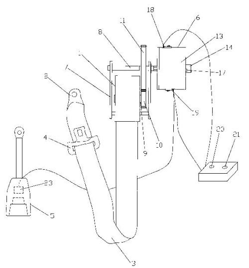
Fig. 1 is the structural representation of the utility model;
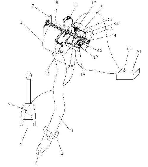
Fig. 2 is the structure diagram when the gear shaft of the utility model is inserted into the sliding shaft spline groove;
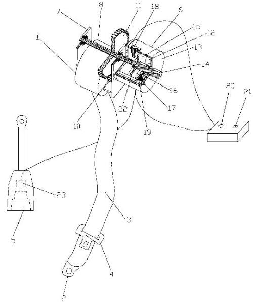
Fig. 3 is a structural diagram of the gear shaft of the utility model when the spline groove of the sliding shaft is disengaged.
Detailed ways
As shown in the figure, the pressure regulating retractor disclosed by the present utility model includes a retractor body 1, and a webbing 3, one end of which is mounted on the retractor body 1, and the other end is fixed on the automobile through a fixing ring 2. The movable tab 4 on the webbing 3 is installed on the car 5 that matches the movable tab 4; the retractor body 1 is provided with a webbing elastic adjustment mechanism 6, and the webbing tension adjustment mechanism 6 is installed on the retractor body 1 A rack 7 is added on the rack 7, the rack 7 is equipped with a gear shaft, that is, a spline shaft 8, the rotating shaft 9 of the retractor body 1 for winding the webbing 3 is lengthened and equipped with a driving gear 10, and the spline shaft 8 of the rack 7 is mounted on the top. There is a driven gear 11 meshing with the driving gear 10; the frame 7 is also equipped with a gear shaft rotation angle controller 12 that controls the rotation angle of the spline shaft 8; the gear shaft rotation angle controller 12 is a device mounted on the frame 7. The casing 13 is equipped with a sliding shaft 14 that can slide in the axial direction. The sliding shaft 14 is fixedly equipped with an iron disc 15 and a rotation angle control rod 16 that can be magnetically attracted by an electromagnet. The blocking rod 17 for the rotation of the angle control rod 16; the first electromagnet 18 and the second electromagnet 19 for attracting the iron disc 15 are installed in the casing 13 in front of the two sides of the iron disc 15, and the first electromagnet 18 and the second electromagnet 19 are installed at a position 180° apart. An electromagnet 18 is connected to a first electric button 20, a second electromagnet 19 is connected to a second electric button 21 and a third electric button 23 installed in the clip 5, the second electric button 21 and the The three electric buttons 23 are connected in parallel with the second electromagnet 19 ; one end of the sliding shaft 14 is provided with a spline groove 22 which cooperates with the spline shaft 8 for transmission.
The working principle of the utility model is as follows: after people sit on the car seat, they wear the webbing on the chest as usual, and insert the movable tabs mounted on the webbing into the buckles mounted on the car. At this time, the webbing is close to people’s chest and abdomen. If the webbing is not close to people’s chest and abdomen, it is necessary to loosen the webbing and press the first electric button. At this time, the electromagnet is instantly energized to generate a magnetic suction iron. If the gear shaft is a spline shaft, the spline shaft will be automatically inserted into the spline groove of the sliding shaft; if the end of the gear shaft is a spline shaft The keyway, one end of the sliding shaft is a splined shaft, then the one end of the sliding shaft that has been slid over will be automatically inserted into the splined groove at the end of the gear shaft. At this time, the rotating shaft of the retractor body for winding the webbing is integrated with the extended driving gear, the driven gear meshing with the driving gear, the gear shaft of the driven gear mounted on the frame, and the sliding shaft installed in the casing, and the sliding The rotation angle control lever on the shaft rotates in the counterclockwise or clockwise direction and is blocked by the blocking rod installed longitudinally in the casing, so that the above-mentioned whole cannot make the retractor body rotate in the direction of tightening, so the tension is loose. The webbing will no longer be tightened by the retractor body; if the webbing is loose enough, the webbing can be loosened, but the length of the webbing can only be loosened by rotating the angle control lever clockwise or counterclockwise. One rotation of the retractor body rotates to release the length of the webbing. If the seat belt is tightened, press the second electric button, at this time the second electromagnet is instantly energized, attracting the iron disc, so that the sliding shaft of the iron disc slides and disengages from the inserted gear shaft, then the coil The body of the receiver returns to an independent working state; if you want to remove the seat belt, when you press the buckle, the third electric button installed in the buckle is turned on, and the second electromagnet is instantly energized, attracting the iron disc. , so that the sliding shaft of the iron-loading disc slides and is disengaged from the inserted gear shaft, and the retractor body also returns to an independent working state.
The utility model is simple in structure and reasonable in design. People wear it on the car without feeling of being bound, and the chest and abdomen will not feel oppressed, which is safe and comfortable; the tightness of the seat belt is automatically adjusted by buttons, and the operation is simple. It is convenient; and the tightness state will not change after adjustment, which is stable and reliable.
 Static Seat Belt
 Universal 2-Point Seat Belt
 Universal 3-Point Seat Belt
 Baby Seat Fittings / Holder
 Seat Belt Extender
 Wheelchair Seatbelt
 Racing Seat Belt
 Seat Belt Tongues/Buckles
 Anchorage Rings
 Anchorage Plate
 Seat Belt Adjuster