Retractor Mounting Mechanism
Claims
- The retractor installation mechanism is characterized in that it includes an outer casing, one side of the outer casing has an opening communicating with its inner cavity, and the outer casing is extended with elongated portions on both sides of the opening, so A movable seat is slidably arranged on the elongated portion, an installation hole is opened on the movable seat, a strip-shaped abdication groove is arranged on the elongated portion at a position corresponding to the installation hole, and the outer casing A positioning protrusion is provided at the opening extending inwardly.
- The retractor installation mechanism according to claim 1, wherein the outer casing, the elongated portion and the positioning protrusion are integrally formed.
- The retractor installation mechanism according to claim 1, wherein a side end of the elongated portion is provided with a bar-shaped groove, and the bottom of the movable seat has a plug-in portion that can be inserted into the bar-shaped groove .
Summary Of Instruction
The utility model discloses a retractor installation mechanism, which is characterized by comprising an outer casing, one side of the outer casing is provided with an opening communicating with its inner cavity, and the outer casing is extended with long strips on both sides of the opening. A movable seat is slidably provided on the elongated portion, an installation hole is opened on the movable seat, and a strip-shaped abdication groove is arranged on the elongated portion at a position corresponding to the installation hole, so The outer casing is provided with a positioning protrusion extending inwardly at its opening. The utility model has the advantages of simple structure and reasonable design, and can conveniently realize the flexible positioning and installation of the retractor.
Manual
Retractor Mounting Mechanism
technical field
The utility model relates to safety belt equipment, in particular to a retractor installation mechanism.
Background technique
The retractor is mainly used for winding and retracting the seat belt. When the retractor is installed, it is often necessary to place the retractor in the outer casing, and then fix the outer casing in the motor vehicle, while the traditional outer casing is often only fixedly provided with mounting holes, while the retractors of different models are installed. There may be a certain deviation in the position of the mounting holes of the casing, which leads to poor generality of the use of the casing, and the internal installation space of different vehicles is also quite different, and it is difficult to realize the flexibility of the casing of a retractor. Install.
SUMMARY OF THE INVENTION
In view of the deficiencies of the background technology, the technical problem to be solved by the present invention is to provide a simple structure and reasonable design, which can conveniently realize the flexible positioning and installation of the retractor.
For this reason, the utility model adopts the following scheme to realize:
The retractor installation mechanism is characterized in that: it comprises an outer casing, one side of the outer casing has an opening communicating with its inner cavity, the outer casing is extended with long strips on both sides of the opening, and the long A movable seat is slidably provided on the bar portion, an installation hole is opened on the movable seat, a bar-shaped abdication groove is arranged on the elongated portion at a position corresponding to the installation hole, and the outer casing is in its position. The opening is provided with a positioning protrusion extending inwardly.
The outer casing, the elongated portion and the positioning protrusion are integrally formed.
The side end of the long portion is provided with a bar-shaped groove, and the bottom of the movable seat has a plug-in portion that can be inserted into the bar-shaped groove.
By adopting the above technical scheme, the utility model has the advantages of simple structure, reasonable design, and large-scale production can be realized; the movable setting of the installation holes can be realized by setting the movable seat, and the threaded holes of the installation positions of the retractor in different vehicles can be arranged according to the movement of the installation holes. The position of the movable seat can be adjusted flexibly to adapt to it, so as to realize the flexible installation of the outer casing of the present application on different vehicle models, and according to the requirements of the internal installation space of different vehicle models, the outer casing can be placed in a position where it is easier to install as a whole. , and then adjust the position of the movable seat so that the installation hole matches the threaded hole for the fixed installation of the retractor, which effectively improves the versatility of its use and facilitates later maintenance and replacement.
Description of drawings
The utility model has the following accompanying drawings:
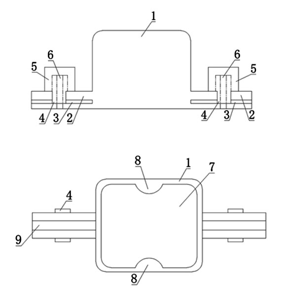
Fig. 1 is the front view of the utility model;
Figure 2 is a bottom view of the utility model.
Detailed ways
As shown in the figure, the retractor installation mechanism disclosed by the present utility model includes an outer casing 1, one side of the outer casing 1 has an opening 7 communicating with its inner cavity, and the outer casing 1 is extended on both sides of the opening 7 with a The elongated portion 2 is provided with a movable seat 5 slidably on the elongated portion 2. Specifically, the side end of the elongated portion 2 is provided with a bar-shaped groove 3, and the bottom of the movable seat 5 has an insert that can be inserted into the bar-shaped groove 3. Connection 4. The movable seat 5 is provided with a mounting hole 6, and the elongated portion 2 is provided with a strip-shaped abdication slot 9 at the corresponding position of the mounting hole 6, so as to ensure that the fastener can pass through smoothly and be screwed with the threaded hole inside the motor vehicle , the outer casing 1 is provided with a positioning protrusion 8 extending inwardly at its opening 7 to ensure that the retractor can be limited by the positioning protrusion 8 after being squeezed into the inner cavity of the outer casing 1 to avoid transportation during transportation. fall out in the process. Further, the outer casing 1 , the elongated portion 2 and the positioning protrusion 8 are integrally formed, which is convenient for the production and processing of the product.
The retractor installation mechanism of the utility model has the advantages of simple structure and reasonable design, and can realize large-scale production; the movable setting of the installation holes is realized by arranging the movable seat 5, and the threaded holes of the installation positions of the retractor in different vehicles can be adjusted according to the installation position of the retractor. The position of the mobile seat can be adjusted flexibly to adapt to it, so as to realize the flexible installation of the outer casing of the present application on different vehicle models, and according to the requirements of the internal installation space of different vehicle models, the outer casing can be placed as a whole in an easier installation. position, and then adjust the position of the movable seat so that the mounting hole matches the threaded hole for the fixed installation of the retractor, which effectively improves the versatility of its use and facilitates later maintenance and replacement.

 Static Seat Belt
 Universal 2-Point Seat Belt
 Universal 3-Point Seat Belt
 Baby Seat Fittings / Holder
 Seat Belt Extender
 Wheelchair Seatbelt
 Racing Seat Belt
 Seat Belt Tongues/Buckles
 Anchorage Rings
 Anchorage Plate
 Seat Belt Adjuster