Summary of the instructions provided Part 2
Attached figure description
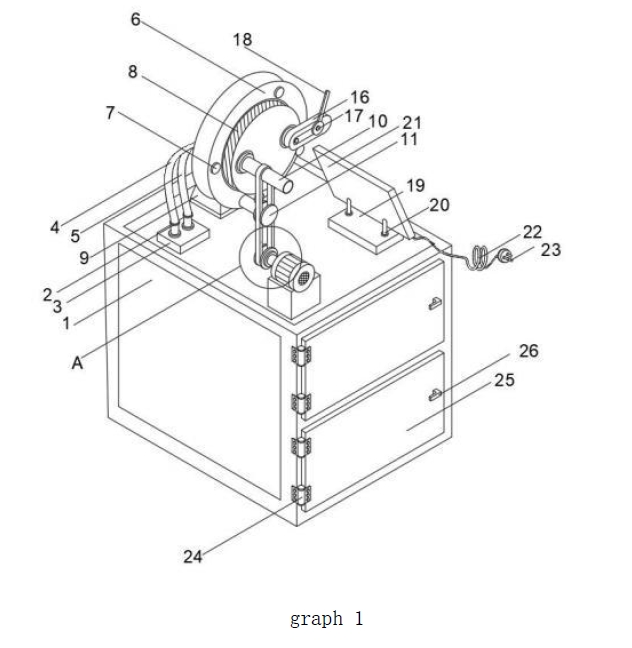
FIG. 1 is a schematic diagram of the utility model;
FIG. 2 is a schematic diagram of the door panel in FIG. 1 of the utility model;
FIG. 3 is an enlarged view of the structure at the position of A, as shown in FIG. 1 of the present utility model.
Figure: 1, detection table; 2, linear joint; 3, bottom plate; 4, rotating line; 5, speed line; 6, rotating wheel; bolt; 8, speed wheel; 9, support frame; 10, guide wheel; 11; coil, fixed plate; 12, ribbon; 13, runner; 14, motor; 15, fixed block; 16, lock; 17, force value sensor; 18, guide rod; 19, plate; 20, support rod; 21,display; 22, wire; 23, plug;24, hinge; 25, door panel; 26, handle.
Specific implementation methods
The technical scheme in the utility model embodiment will be clearly and completely described in the following in combination with the attached drawings in the utility model embodiments, and obviously, the described embodiments are only part of the utility model embodiment, not all embodiments. Based on the embodiments in the utility model, all other embodiments obtained by ordinary technicians in the field without making creative labor are within the scope of the protection of the utility model.
Referring to FIGS. 1 to 3, the embodiment of the utility model
place, Including the test table 1, The top of the detection table 1 is fixed with the bottom plate 3, The surface of the bottom plate 3 is fixed with two linear joints 2, The top of the linear joint 2 is fixed with the rotation line 4 and the speed control line 5, The top of rotation line 4 is fixed with rotating wheel 6, The bottom of the rotating wheel 6 is fixed with a support frame 9, The surface of the rotating wheel 6 is fixed with bolts 7, The top of speed control line 5 is fixed with speed wheel 8, The surface of speed wheel 8 is fixed with guide wheel 10, The surface of the guide wheel 10 is in contact with the ribbon 12, The inner side of the belt 12 is connected with the retractor fixing plate 11, The bottom fixed attachment of the belt 12 has a runner 13, reel
13 has a surface fixed connection with a motor 14, The bottom of the motor 14 is connected with a fixed block 15, Surface surface attachment value sensor 17, Force value sensor 17 has surface fixed connection locking member 16, The locking member 16 is surface fixed with a guide rod 18, The detection table 1 is fixed with a flat plate 19, The surface of the plate 19 is fixed with support rod 20, The surface of the support rod 20 is fixed with a display 21, The bottom fixed attachment of the display 21 has a wire 22, The bottom connection of wire 22 has plug 23, The surface fixing connection of the detection table 1 has a hinge 24, The surface of the hinge 24 is fixed with the door panel 25, The surface of the door plate 25 is fixed with a handle 26.
among, Fixed connection between the plug 23 and the display 21 by the electric wire 22, Between the display 21 and the flat plate 19 by the support rod 20, Easy to display the test results when used, More intelligent, The linear joint 2 and the rotating wheel 6 are fixed by the rotating line 4, And the surface of the rotating wheel 6 is firmly connected to the bolt 7, It is convenient to rotate the rotating wheel 6 to drive the guide wheel 10 to tilt at different angles, Between linear connector 2 and speed wheel 8 by speed control line 5, And the surface of the rotation speed wheel 8 is rotation connected with the rotating wheel 6, Easy to rotate the rotating speed wheel 8 to tilt the guide wheel 10 at different speeds, The door panel 25 and the detection table 1 are fixed by the hinge 24, The surface of the
door plate 25 is firmly connected to the handle 26, Use is easy to increase storage space and repair internal parts, The surface of the guide wheel 10 has a convex bar, And the surface of the bump is in contact with the surface of the ribbon 12, To facilitate the automatic fixed point of the ribbon 12, The surface of the retractor fixing plate 11 is in contact with the retractor, And the surface of the ribbon 12 contacts the force value sensor 17, It is easy to record the locking angle when used.
The working principle of the utility model is that, when testing, First, install the retractor on the retractor fixing plate 11 at the loading angle, Passing the belt 12 through the guide wheel 10, Attach the force value sensor 17 across the belt
12 to the winding wheel 13 of the belt 12, starting device, Pluplug 23 into power by wire 22, Motor 14 drives the whole system to rotate at a certain angular speed, The rotation wheel 6 and the rotation speed wheel 8 are connected to the speed control line 5 by the rotation line 4, Not only can we record the detection of multi-angle winding angle tilt locking at different speeds, While the belt 12 winding wheel 13 rolls the belt 12 at a set linear speed, When the inclination reaches a certain angle, the retractor begins to lock through the locking piece 16, Ribbon
12 increases the force value sensor 17
At the preset value, the display 21 system notes the angle at this time, and the inclination and the belt 12 and the motor 14 simultaneously return to the initial position. By testing in another direction, the door plate 25 and the detection table 1 are connected by the hinge 24, the surface of the door plate 25 is connected to the handle 26 to increase the storage space and repair the internal parts, the surface of the guide wheel 10 is provided with a convex, and the surface of the convex contacts with the surface of the ribbon 12 to facilitate the automatic fixing of the ribbon 12.
The above, only for the better embodiment of the utility model, but the protection scope of the utility model is not limited to this. Any technical personnel familiar with the technical field within the technical scope of the technical scheme of the utility model, shall cover the protection scope of the utility model.


 Static Seat Belt
 Universal 2-Point Seat Belt
 Universal 3-Point Seat Belt
 Baby Seat Fittings / Holder
 Seat Belt Extender
 Wheelchair Seatbelt
 Racing Seat Belt
 Seat Belt Tongues/Buckles
 Anchorage Rings
 Anchorage Plate
 Seat Belt Adjuster